How to prepare an irrigation design: a step-by-step guide
A landscape irrigation design is a plan showing which area is irrigated how, where the heads go, which head connects to which valve, what size the pipes are and how long the system runs. With a good design the water is distributed evenly, no water is thrown onto paths and walls, and the pump and pipes are neither oversized nor undersized.
1. Separate the areas: what is irrigated, and how?
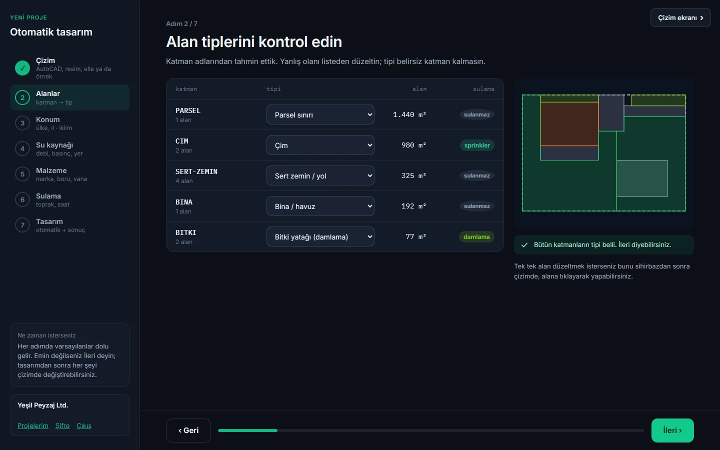
First split the garden into area types. Lawns are irrigated with sprinklers (spray or rotor). Planting beds and tree bases get drip; no turf irrigation where there is drip. Buildings, pools, paths and hardscape are not irrigated and must not receive spray.
2. Measure the water source: flow and pressure
The water source sets the limits of the design. Measure the flow (m³/h) and pressure (bar) available from the mains or the pump. A zone's total flow cannot exceed this value, and the farthest head must still have its operating pressure.
3. Choose the head type: spray or rotor?
- Spray nozzle: for narrow and small areas (about 1–5.5 m radius). High precipitation rate, short run time.
- Rotor: for large lawns (about 7.5 m and more). Low precipitation rate, long run time.
- Rotary nozzle: fits a spray body; a low precipitation rate middle option.
Because their precipitation rates differ, sprays and rotors are never put on the same valve.
4. Place the heads: start from the corners
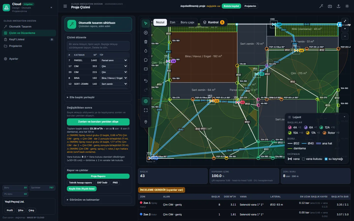
Layout starts at the corners: a corner head's arc equals the corner angle (a quarter circle for a 90° corner). Then the edges, and finally the interior. Head spacing is usually equal to the radius ("head-to-head"): each head's water must reach its neighbour, otherwise dry strips remain. Edge heads must not spray outside the area, especially onto paths and buildings.
5. Split into zones and place the valves
Heads that run at the same time form a zone. A zone's total flow must not exceed what the source can deliver, and the heads in a zone should have similar precipitation rates. Valves are placed near the middle of the zone in an accessible spot and grouped in a valve box.
6. Size the pipes and calculate the pressure
Pipe size is chosen by the flow it carries: larger flow, larger diameter, tapering towards the end. PE100 PN10 pipe is common in landscape irrigation in Türkiye. Pipe velocity is usually kept around 1.5 m/s. Friction loss to the farthest head, valve loss and elevation difference are calculated; the farthest head must still have its operating pressure.
7. Set run times from the climate
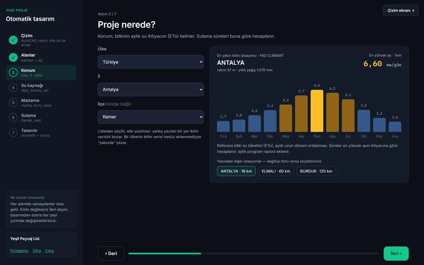
Plant water demand is calculated from the evapotranspiration (ETo) of the hottest month. Dividing this demand by the heads' precipitation rate gives each zone's run time. Watering is scheduled at night when wind and evaporation are low; soil type determines how fast water infiltrates.
8. Compile the bill of materials
Finally the material list is prepared: heads and bodies, pipes (with waste allowance), fittings, valves, valve boxes, controller, wire. This list is the basis of the quotation.
Do all of this in minutes
OtomatikSulama does all these steps for you: upload your AutoCAD drawing or a sketch, make a few choices; head layout, zoning, pipe sizes, pressure calculation, irrigation schedule, project report and priced bill of materials come ready. You review the result and adjust it in the drawing as you like.
Note: calculations are a preliminary design; verify on site with pressure and flow measurements before construction.